MarcoSlim


New version MarcoX is available here : MarcoX
Preface
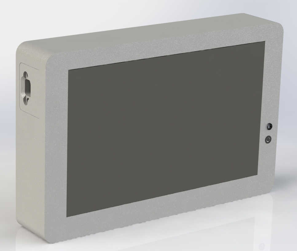
MarcoSlim is an upgrade of original Marco. Project had been launched during the 2023 BDE of Télécom Physique Strasbourg. Original Marco was based on Raspberry PI and old style resistive screen and 3 meters of cables and adapters hardly stuff in rectangular 3D printed case.
This new version is based on Orange PI zero 2W with a 7" capacitive touch screen. This modernized versiona aims to be more reliable and compact with a new RFID reader.
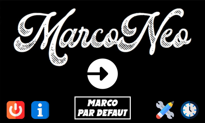
Software was also modernized and is available here : https://github.com/LOISGALLAUD/MARCONEO
Marco is a project that aims to create a payment terminal for a school BDE (French equivalent of Student Union). It is based on a RFID card system. The terminal is used by the students to pay for their meals or drinks. The terminal is connected to a self-hosted server that manages the accounts of the students. This terminal act as cash register.
This project is related to InsidePSBS app. Students can check their account and history on this mobile app available on IOS and Android. https://github.com/info-telecom-strasbourg/InsidePSBS (Reserved to TPS and ESBS students)


Specifications
- Screen: 7" capacitive touch screen
- RFID reader: 125kHz compatible
- Power supply: USB-C 5V 3A
- SBC: Orange PI zero 2W
- SoC: Allwinner H618 quad-core Cortex-A53 @ 1.5GHz
- RAM: 1GB LPDDR4
- Wi-Fi: 802.11 ac (Wi-Fi 5)
- Bluetooth: 5.0
- Battery: 29.6Wh Li-ion (4x 3.7V 2000mAh)
- Dimensions:
- Length: 200mm
- Depth: 129mm
- Height: 38mm
Shopping list
Electronic parts
Orange PI zero 2W with 1GB RAM or more
Micro SD card 16GB ore more, U3 speed class or more
7" Waveshare touch screen or compatible with HDMI input
125kHz RFID reader
4x 3.7V 2000mAh Li-ion battery
USB-C power supply
mini HDMI to HDMI 100mm cable: A2 to C1
USB-C to micro usb 100mm cable: W3R to T1B
USB-C pannel 17mm center distance mount connector 20mm
Mechanical parts
M4 screws 16mm x4
M4 inserts x4
M3 screws 10mm x15
M3 inserts x15
Parts details
| Orange PI zero 2W |
|
| Mini HDMI to HDMI 100mm cable: (A2 to C1). Large side of HDMI is on ribbon cable side. Mini HDMI large side is on ribbon connector side. |
|
| USB-C to micro usb 100mm cable: W3R to T1B |
|
| USB-C pannel 17mm center distance mount connector 200mm |
|
Screen
Screen is 7" Waveshare touch screen or compatible with HDMI input it can be a compatible one as long as it has the same connectors and the same size.


3D printed parts
All parts are in .stl format. They are designed to be printed without support.
Printer settings
Tested settings, but feel free to adapt them to your printer and material.:
- Layer height: 0.2mm
- Infill: 20%
- Nozzle diameter: 0.4mm
- Material: PLA or PETG
Note: PTEG is recommended for better water and UV resistance.
All parts


Front
File: front.STL
The front cover hold the screen and allow it to be attached without overthickness. It also includes the RFID reader coil use for card detection, USB-C charging hole, power activity LED and Power button. This part is attached to the enclosure with 4 M4 screws, and provide a sort of seal to prevent dust and water to enter the enclosure.
Note: clearance for sealing are very tight. This make 3D printing more difficult and printer dependent.
Internal frame
File: internal_frame.STL
This frame is attached to the screen and is used to mount Orange PI, Li-ion batteries, PCB and Wi-Fi antenna.
Note: For this part adding support may improve print quality
Cover
File: cover.STL
The back cover is used to close the enclosure. It is attached to the enclosure with 4 M4 screws.
Note: clearance for sealing are very tight. This make 3D printing more difficult and printer dependent.
Miscellanous
Orange PI Standoff
File: orange_pi_standoff.STL
Standoff are used to maintain Orange PI in place and add spacing for electronics components bellow. They are attached to the internal frame with 3 M3 screws.
Battery holder
File: 18650_4_holder.STL
Battery holder is used to maintain 4 Li-ion batteries in place. It is attached to the internal frame with 4 M3 screws.
Electronics
RFID reader
RFID reader is connected to Orange PI with either USB if the reader use is the classic USB reader that act as a keyboard or GPIO if the reader is custom made on PCB.
The RFID coil is placed in the front cover arround the screen. By this way the card can be detected by the reader when the card is hold in the user hand when he interact with the screen. This is a way to make the user experience more intuitive. Coil is connected to a tiny PCB with a connector that is attached to the front cover with 2 M3 screws. (see front cover bellow)
But the screen is made with a large metal plate that disturb the magnetic field of the coil. After multiple tests this idea was abandoned in favor of a more classic placement of the coil with the new MarcoX version.
Power button and activity LED
Power button is connected to PCB with a 2 pin connector and trigger Orange PI zero 2W boot. It is placed in the front cover and is used to power on and off the terminal.
Activity LED is bicolor and connected to PCB with a 3 pin connector. It is placed in the front cover to indicate the charging status of the terminal.
Related projects
New version MarcoX is available here :
Software associated with MarcoX is available here :


Mobile App InsidePSBS source is available here :


